CH376 USB Development Board
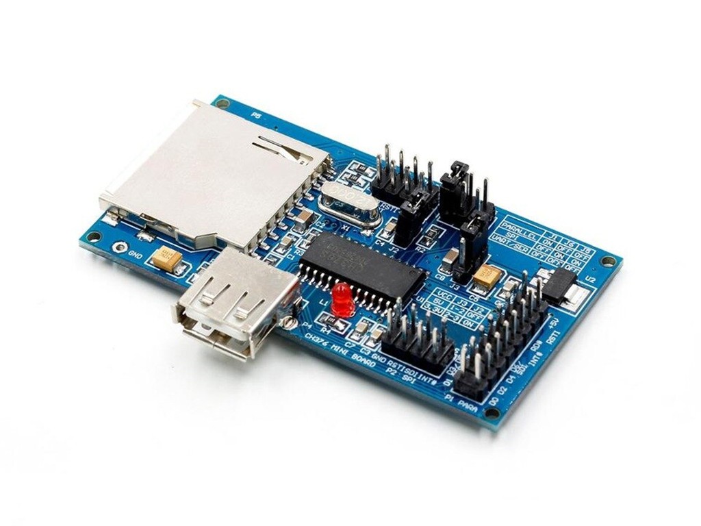
The main devices U1 of evaluation board is CH376 USB Development Board, but in some signal is name from CH375 or CH374.
-Crystal X1 as the standard 12MHz, USB host than USB equipment required frequency accuracy higher, X1 error is less than 0.4 ‰, 12MHz crystal can basically meet the requirements of general. Strongly recommend that related to the shortening of the wire length, in order to reduce the interference.
-Capacitor C4 for internal power decoupling to reduce USB transmission process of EMI, the capacity of 4700pF to 0.1uF, you can choose 103 SMD capacitors 0.01uF ordinary.
-P5 is a SD card socket, can reach the standard size of the SD card, the other specifications of the SD card can need additional conversion base. R3 for the current limit resistor output to external SD card, avoid the short time caused by power supply voltage in the SD Kagan inserted down.
-P1 is a 8 bit parallel port used to connect the signal, the parallel port, the necessary signal parallel including D0-D7, A0, RD#, WR#, CS# and GND, while the INT# is optional.
-P2 is a signal port SPI serial port, SPI interface for connecting one of the microcontroller, the necessary signal SPI including SCS, SCK, SDI, SDO and GND, while the INT# is optional.
-J3 is used to select the CH376 chip voltage, short circuit to 1-2 feet 5V voltage, short circuit to 3.3V voltage 2-3 pin. The default for 5V voltage, when the voltage is equal to or lower than the single chip 3.3V, can choose 3.3V voltage CH376. Working voltage when the CH376 chip 5V, J2 must be disconnected, the working voltage when the CH376 chip 3.3V, J2 must be short.
J1, J5 and J6 is used to select the communication interface of CH376 and single-chip microcomputer in the power or hardware reset:
-If the J1 short, J5 off, J6 off, so is a 8 bit parallel port;
-If the J1 is disconnected, J5 shortened, J6 shortened, so is the SPI interface;
-If the J1 off, J5 off, J6 off, so is the asynchronous serial port.
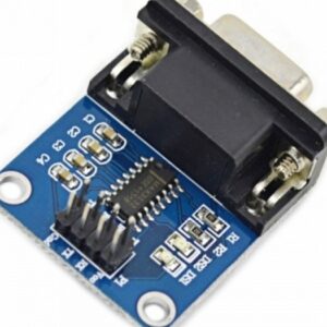
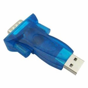
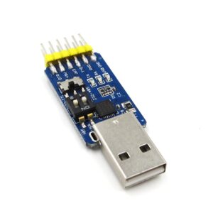
-Some examples of procedures may be debugging information using the serial output, if the need to display the monitoring information, can be the serial after RS232 conversion and connected to a computer using serial port monitoring / debugging tools to view. If you use the CH376 USB Development Board, the J2 can be connected to the serial port of computer; if the computer is not the serial port, serial port has been occupied or other equipment, then by the USB to serial chip CH341 serial port emulation.
-CH376 USB Development Board internal devices operate from a supply voltage is 5V, must add the resistance R0 and remove the 3.3V regulator D4, working in the supply voltage is 3.3V, must add the regulator D4 and remove the resistance of R0. The default is 5V power supply.



There are no reviews yet.