4X4 Matrix Switch Keypad
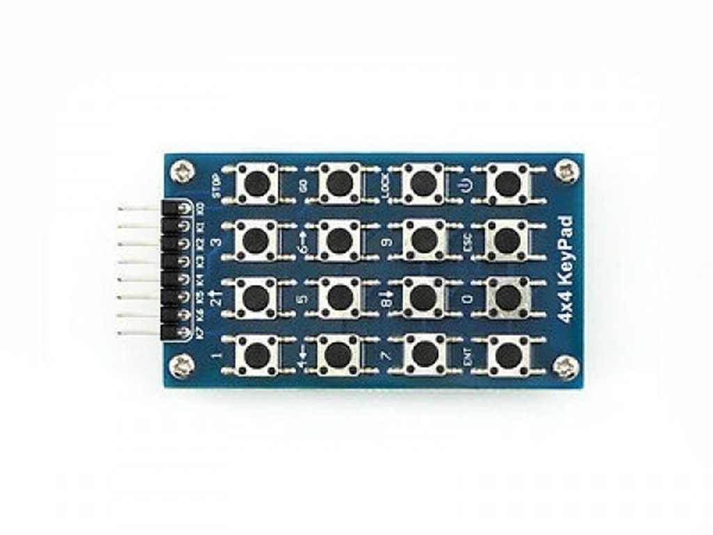
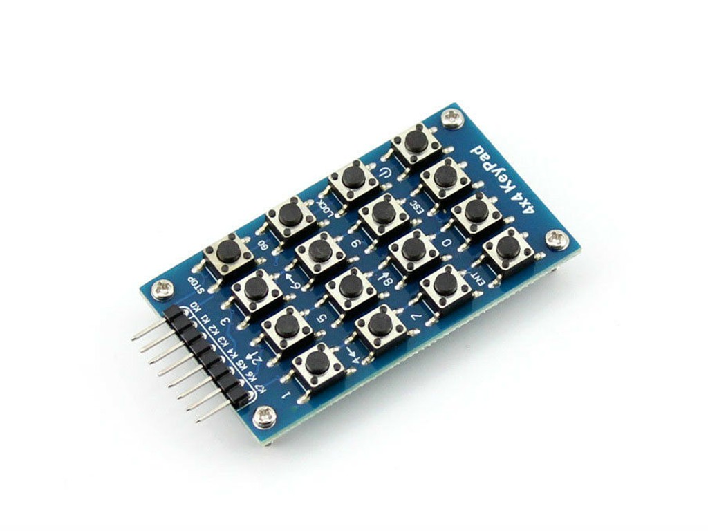
The 4×4 matrix Switch keypad is commonly utilized as an input device for projects. With a total of 16 keys, it provides a wide range of input options. This non-encoded module features a parallel arrangement of 16 keys and uses designated pins (R1-R4 for rows and L1-L4 for columns) to control their functions.
The 4×4 matrix Switch keypad includes microswitch buttons and four 3mm (M3) mounting holes. Each PCB displays the designated pins for easy reference, with four serving as the “x” coordinate and the remaining four as the “y” coordinate.
The module comes pre-installed with soldered pin headers that are rotated 90 degrees.
The process:
Begin by checking if any key is currently pressed down. Apply power to the rows, so they are at a High level. Proceed by setting all of the rows, R1-R4, to Low and then observe the status of the columns. If any column is Low, this indicates that a key is being pressed down and it can be found among the 4 keys in that column. On the other hand, if all of the columns are High, no keys are being pressed down. Then, proceed to locate the specific key being pressed. Since we have already identified the column in which the key is located, determining the row will complete our testing process. To do this, set each row to Low one at a time until we find which one corresponds with the pressed key – while keeping all other rows High.
At this point, it is possible to identify the row. Proceed to determine the status of each column one by one. The “Low” column is the intersecting one with the line, and its cross point corresponds to the key that was pressed.
Included in the package are a variety of impressive features.
- The 4×4 Matrix Switch keypad Module features 16 buttons.
- Compact in nature, thus conserving space.
- Easier to utilize
- Increased the range of development application modules available for a single chip.
- Featuring a total of 16 keys and 8 pin, this device offers ample options for ease of use.









There are no reviews yet.