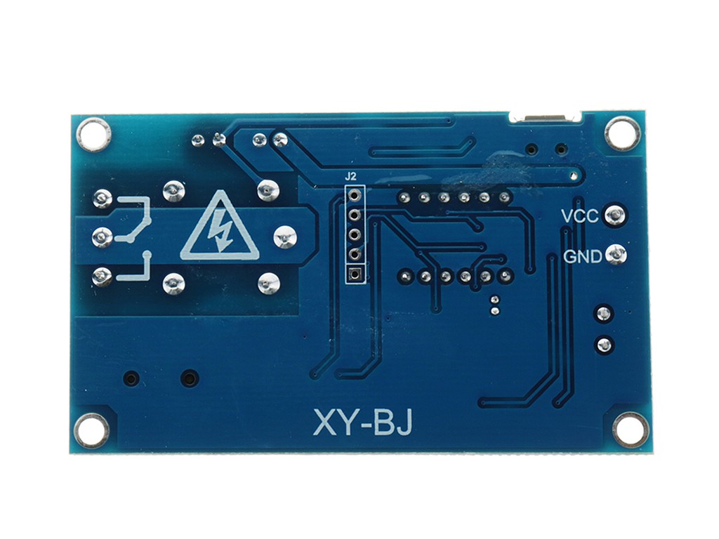

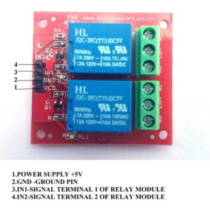
5V Digital Display Real Time Delay Relay Switch Controls
The paragraph describes the use of a new 5V Digital Display Real Time Delay Relay Switch Controls that has been implemented in a company’s daily operations.
Key features of the 5V Digital Display Real Time Delay Relay Switch Controls include:
- The power supply has a voltage range of 5.0V to 60V.
- One mode has the capability to establish up to 5 different time periods.
- 5V Digital Display Real Time Delay Relay Switch Controls includes a buzzer alarm feature.
Introduction to function modes:
- Please provide the closing time for OPE and the opening time for CLE.
- The time periods of PE-1 to PE-5.
- Shield function
- The OPE relay sends a closing output pulse every day, while the CLE relay remains open and also sends an output pulse.
- The OPE relay is currently closed and will remain so until the day the CLE relay opens, at which point an output pulse will be generated.
- During certain periods of the month, the OPE relay will be closed and the CLE relay will be open, resulting in output pulses being produced.
- Throughout a couple of months, some digits were added and subtracted on a daily basis, from the beginning to the end: OPE for shutting off relays or emitting pulses and CLE for disconnecting relays or emitting pulses.
- The monthly output pulse occurs multiple times per day at various start and end points, specifically when the OPE relay is closed and the CLE relay is open.
- Kindly take note of the time and date when operations will begin (OPE) and conclude (CLE).
- 5V Digital Display Real Time Delay Relay Switch Controls
Instructions on how to adjust the time:
- When utilizing the time running interface, simply hold down the DOWN button.
- Upon entering the time setting interface, the system will display “YEA” and begin flashing. The two digits following “year” can be adjusted by utilizing the DOWN and UP buttons (with long press support).
- To enter the “Month/Day” setting interface on the SET system, briefly press the button and “dAE” will appear. The “Month” can be adjusted using the DOWN or UP buttons (long press is also supported) and should be flashing.
- Push the SET button to adjust the “day” value by either pressing UP or DOWN (long press is also supported).
- After pressing SET, the system will display ‘HOU’ and enter the interface for setting the hour and minute. The hour section will then continuously blink and can be adjusted by using the DOWN and UP buttons (with long press support).
- Press SET briefly to make the “minute” flash. Use DOWN and UP buttons (hold down for extended adjustment) to make necessary changes. Repeat step 1 by pressing SET briefly once again.
- After a long press of the SET button to release, the time will be adjusted based on the specified parameters. This will also exit the time setting interface.
- 5V Digital Display Real Time Delay Relay Switch Controls
Setting the parameters can be done by following these steps.
- To access the parameter setting interface, hold down the SET button for 2 seconds in the time running interface before releasing it.
- To begin, choose the time period you would like to view by pressing the DOWN button. The options available are PE-1 through PE-5.
- Next, choose the mode for Step 2 by pressing the UP and DOWN buttons. The mode options are labeled as P-1 through P-5, so select the one that corresponds to your desired time period. Keep in mind that choosing “—-” will block this time period.
- Please take into consideration the following guidelines to ensure that your project meets all of the necessary requirements.
- The recurring sequence for each time period can be chosen from “—-“, P-1 ~ P-5. For instance, you can have 5 segments operating in P-1 mode simultaneously, or assign segment 1 to work in P-1 mode while segment 2 operates in P-2 mode, and so on. This flexibility allows for convenient customization based on your specific requirements.
- Following the mode selection, press SET to enter the time period setting interface. Within this interface, use a short press on SET to toggle between the parameters: “OPE” for start time, “CLE” for end time, and “dAE” for date information.
- After setting the parameters, exit by holding down the SET button for 2 seconds and releasing it. The valid parameters will be saved and you will return to the operation interface. If there is an error with the parameter, an “ERR” reminder will appear and you will be taken back to the parameter setting interface. Please note that the stop time / date cannot be before the start time / date (CLE > OPE).
Other features include the option to set a specific time period of your choice.
- In the parameter setting interface, short pressing STOP after the second step will switch the output mode.
- The relay is activated by the start point and deactivated by the end point.
- The output at the designated time will result in a 1-second pulse.
- hold the “Save” button, then click on
- Press the STOP button to change the ringing setting to bLL0, which will disable the ringing.
- Ringing has been activated.
- Upon hearing the ring, simply press any button to silence it.
- Enhance the capabilities of the STOP button:
- Either change the relay to enable mode or put it in enable position.
- The relay is activated during the designated time period.
- OFF: The relay must always remain off and should not be activated.
- 5V Digital Display Real Time Delay Relay Switch Controls cannot conduct while the alarm function is activated, which is only possible after selecting the mode.
- 5V Digital Display Real Time Delay Relay Switch Controls
Entering sleep mode:
- When in CP sleep mode, the digital tube display will automatically turn off after five minutes of inactivity, while the program continues to run as usual.
- In normal mode, the digital tube continuously displays information.
- 5V Digital Display Real Time Delay Relay Switch Controls

There are no reviews yet.