

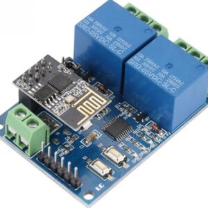
Description:
Module highlights:
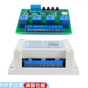
-wide voltage power supply 5.0V–60V;
-one mode can set multiple time periods, up to 5 time periods;
-with buzzer alarm function.
Function mode introduction:
OPE: relay closing time CLE: relay opening time
period: PE-1 to PE-5, 5 time periods
function shield
P-1: OPE relay closing / output pulse every day CLE relay open / output pulse
P-2: OPE relay closed / output pulse on the day CLE relay open / output pulse
P-3: several days of the month: OPE relay closed / output pulse CLE relay open / output pulse
P- 4: during a few months a few numbers to a few months a few numbers, a few start of each day, to end points: OPE closed relay / pulse output CLE disconnect relay / pulse output
P-5: monthly few numbers to a few numbers a few day Start and end at several points: OPE relay closed / output pulse CLE relay open / output pulse
Note: Stop time / date (CLE)> Start time / date (OPE)
I. How to set time
in time running interface, long press DOWN :
1. The system flashes and displays “YEA†to enter the time setting interface. At this time, the two digits after “year†flashes, and can be adjusted by DOWN and UP (support long press);
2. Short press the SET system and flash “dAE†to enter “ “Month / Day” setting interface, “Month” is not Flashing through DOWN, UP adjustment (support long press);
3. Press the SET, at this time, “day” flashes through DOWN, UP adjustment (support long press);
4. Press the SET, the system flashes ‘HOU’ after Enter the “hour / minute” setting interface, at this time the “hour” blinks continuously, and can be adjusted by DOWN and UP (support long press);
5. Press SET shortly, and the “minute†flashes at this time. Adjust by DOWN and UP (support long press). Press SET shortly and repeat step 1 at this time.
6. After long press SET to release, the time will be modified according to the set parameters, and Exit the time setting interface;
2. How to set the parameters
In the time running interface, press and hold the SET button for 2 seconds and let go. The system enters the parameter setting interface:
Step 1: Select the time period: PE-1 ~ PE-5. DOWN button to select;
Step 2: Select mode: “—-” P-1 ~ P-5 (that is, set this time period to the corresponding mode) Press the UP and DOWN buttons to select; ( “—-” means to block this time period)
Note:
The repeating pattern of each time period can be selected from “—-“, P-1 ~ P-5; for example: 5 times Segments work in P-1 mode at the same time, or let time segment 1 work in P-1 mode, time segment 2 work in P-2 mode, etc .; it is very convenient and flexible, and can be arbitrarily combined according to your needs; the
third step : After the mode selection is completed, short press SET to enter the time period setting interface. In the time period setting interface, short press SET to switch the parameters, “OPE†Time of origin, “CLE” end time point, “dAE” date information;
Step 4: Exit the parameter settings, press the SET button for 2 seconds let go, the legality of the detection parameters, valid parameter is saved, return time Operation interface; if the parameter is wrong, it will display “ERR†reminder (stop time / date <= start time / date will report an error) to return to the parameter setting interface;
Note: stop time / date (CLE)> start time / date (OPE)
Additional functions: Any time period can be set individually
in the specific parameter setting interface (after the second step), short press STOP to switch the output mode:
OUT1: start point turns on the relay, end point turns off the relay
OUT2: time point outputs 1S pulse
In the specific parameter setting interface (after the second step), press and
hold STOP to switch the ringing mode: bLL0: Ringing disabled
bLL1: Ringing enabled
Note: After ringing, press any button to stop the ringing
STOP button Function expansion:
relay enable mode:
1. ON: relay is turned on within the relay on time;
2. OFF: relay is forbidden to be turned on and is always off;
short press the STOP button on the time display interface to achieve ON and OFF To switch between them, the current state will blink, and then return to the main interface. (This function is an emergency stop function. One button opens and closes the relay.) When the
relay is prohibited from conducting, the alarm function is set after the mode is set.
Sleep mode:
1. CP sleep mode: within five minutes without any operation, the digital tube automatically turns off the display and the program runs normally;
2. Od normal mode: the digital tube always turns on the display;

There are no reviews yet.