Current To Voltage Isolation Converter Module
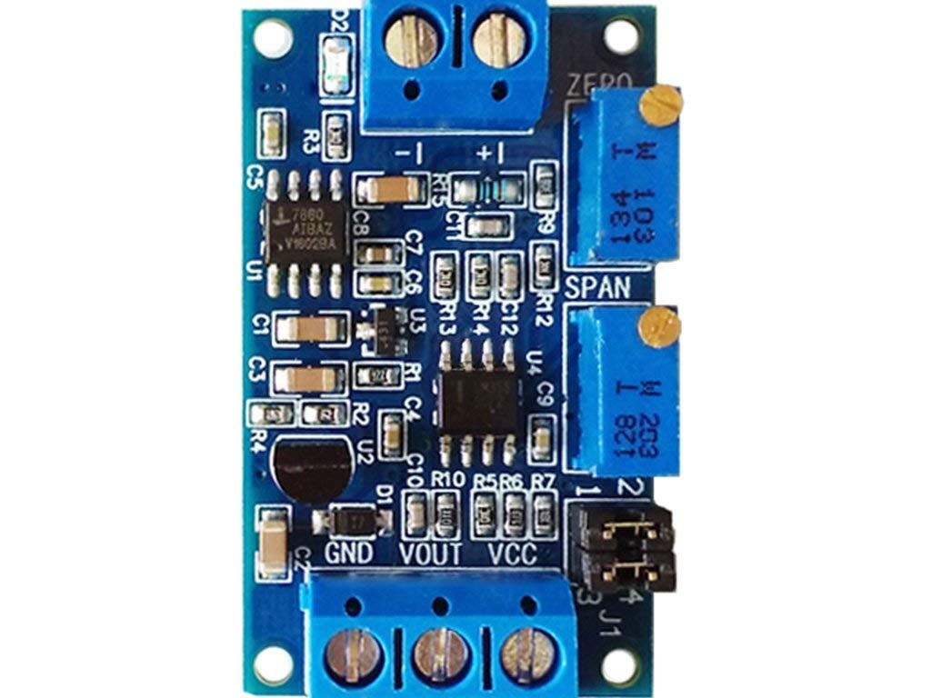
During circuit signal transmission, the voltage will naturally diminish over distance. To prevent this, current transmission is utilized. Current To Voltage Isolation Converter Module converts the current signal into a voltage signal for single-chip detection at the receiving end. It supports a range of 4-20mA and 0-20mA for current input and 0-3.3V, 0-5V, and 0-10V for voltage output.
Characteristics of Current To Voltage Isolation Converter Module:
- The output has various ranges to accommodate a wide supply voltage range.
- Both zero and range are adjustable.
- Current To Voltage Isolation Converter Module offers excellent stability and linearity, making it suitable for industrial use.
- The sampling resistor for the current signal boasts high precision color ring resistance, minimal temperature drift and a robust power capacity.
- The application is a vital step in the process. It must be completed thoroughly and accurately to ensure proper consideration.
- This Module is employed for transforming current signals into voltage outputs.
User guidelines for Current To Voltage Isolation Converter Module:
- As per the wiring specifications, the module operates within a power supply range of 7-36V. However, if the output needs to be set at 10V, the minimum required supply voltage is 12V.
- Upon startup, the D2 light should be illuminated. If not, please inspect the line connection. The board is equipped with reverse protection to prevent burning in case of reverse polarity.
- When the current input is at its lowest (0mA or 4mA), tune the ZERO potentiometer accordingly to ensure the VOUT output remains at its lowest reading (0.0V or other voltage).
- At maximum input (20mA), adjust the SPAN potentiometer to ensure that VOUT output reaches its peak of 3.3V, 5V, or 10V (with a minimum output of 2.5V when input is 4-20mA).
- Based on your requirements, use the jumper cap to choose the suitable range.
- The 4-20mA standard is a form of current loop that is used for transmitting analog signals. This standardized method employs a 4mA minimum and a 20mA maximum current to represent varying levels of the signal.
- The J1 1,2 pin and the 3,4 pin are both short circuit connected.
- J1 pins 1 and 2, as well as 3 and 4, are both disconnected with a voltage range of 0-3.3V.
- The pins 1 and 2 of J1 are connected by a short circuit, as well as the pins 3 and 4. Both sets of pins have been paired and connected together.
- The 0-10V pins are configured as follows: J1 pins 1 and 2 are linked together, while J1 pins 3 and 4 are unconnected.
- 0 to 20 milliamp.
- The J1 1,2 pin and the 3,4 pin are both short circuit connected with a voltage range of 0-3.3V.
- The 0-5V on J1 has a short circuit connection between pins 1 and 2, as well as between pins 3 and 4.
- The 0-10V connection involves J1 pins 1 and 2 being short-circuited, while pins 3 and 4 are not connected.


There are no reviews yet.