Esplora Arduino game controller
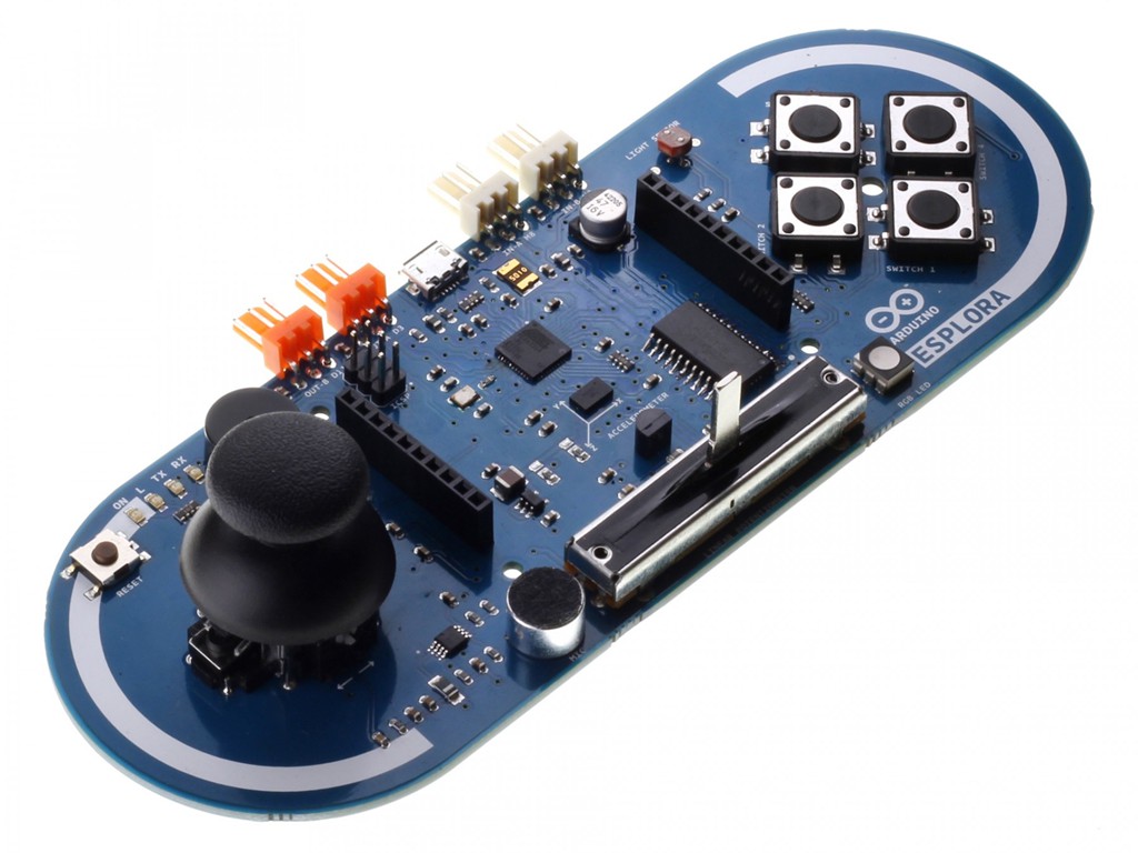
The ESPLORA Arduino game controller Board is an Arduino-compatible microcontroller board based on the Arduino Leonardo. Unlike previous models, it comes equipped with a variety of built-in sensors for immediate use in interactions.
This guide is perfect for individuals interested in using Arduino, but who don’t want to dive into electronics right away. To learn how to use the ESPLORA Arduino game controller Board in a simple and clear manner, be sure to read the Getting Started with Esplora guide.
The ESPLORA Arduino game controller Board boasts onboard sound and light outputs, as well as multiple input sensors such as a joystick, slider, temperature sensor, accelerometer, microphone, and light sensor. Additionally, it offers the option to enhance its functions through two Tinker-kit input and output connectors and a socket for a color TFT LCD screen.
Similar to the Leonardo board, the ESPLORA Arduino game controller Board also utilizes an Atmega32U4 AVR microcontroller with a 16 MHz crystal oscillator. It features a micro USB connection that can function as a USB client device, such as a mouse or keyboard. Additionally, there is a reset push button located in the upper left corner of the board for restarting purposes.
- There exist four indicators, each displaying a different status.
- The green indicator shows if the board is currently being powered.
- The L [yellow] connects directly to pin 13 on the micro-controller for easy accessibility.
- The [yellow] LED indicates data being transmitted or received through the USB connection.
Within the board lies all the necessary components to support the microcontroller. To begin, just connect it to a computer using a USB cable. The ESPLORA Arduino game controller Board is also equipped with built-in USB communication, allowing it to function as a mouse or keyboard when connected to a computer. It also offers a virtual serial/COM port (CDC). This alters the behavior of the board, which is further explained on our getting started page. On this page, you can find all the instructions for configuring your board and utilizing the Arduino Software (IDE) for coding and electronics experimentation.
The transfer of data, both in and out.
- The ESPLORA Arduino game controller Board features a classic gamepad design, including an analog joystick on the left and four push buttons on the right. It also comes equipped with several onboard inputs and outputs:
- The analog joystick features a center push-button and two axes, designated as X and Y. There is also a central pushbutton for added functionality.
- Arranged in a diamond formation are 4 push-buttons.
- The slider for the linear potentiometer is located towards the bottom of the board.
- A tool to capture the volume (amplitude) of the surrounding environment.
- A sensor that detects light to measure brightness.
- The temperature sensor measures the surrounding temperature.
- A three-axis accelerometer detects the orientation of the board with respect to gravity, along the X, Y, and Z axes.
- The buzzer has the ability to generate square-wave tones.
- The RGB LED features Red, Green, and Blue elements that allow for color mixing and a bright display.
- The TinkerKit Inputs allow for easy connection between the sensor modules and 3-pin connectors.
- The TinkerKit Outputs allow for easy connection of the TinkerKit actuator modules via the 3-pin connectors.
- The TFT display connector can be used for a color LCD screen, SD card, or any other devices utilizing the SPI protocol.
To fully utilize all available sensors, the board employs an analog multiplexer. This way, multiple input channels (excluding the 3-axis accelerometer) can share a single analog input of the microcontroller. Selecting which channel to read is done through four additional pins on the microcontroller.
Communication is essential in any relationship, whether it be personal or professional. It plays a crucial role in maintaining strong connections and fostering understanding between individuals. Effective communication allows for open and honest dialogue, facilitating problem-solving and building trust. Without good communication, misunderstandings can occur, leading to conflicts and strained relationships. Therefore, it is important to prioritize effective communication in every aspect of our lives.
The ESPLORA Arduino game controller Board for the Leonardo offers various features for connecting with a computer, another Arduino, or different micro-controllers. The ATmega32U4 enables serial (CDC) communication through USB and is recognized as a virtual com port on the computer. It also functions as a full speed USB 2.0 device and can be used with standard USB COM drivers. A .inf file is needed for Windows.
The Arduino software comes equipped with a serial monitor for easy transmission of text data to and from the board. Whenever data is being sent via the USB connection to the computer, the RX and TX LEDs will light up on the board. Additionally, the ATmega32U4 has SPI capability accessible through the SPI library. In addition, the Esplora can act as a standard keyboard and mouse, allowing you to use programming to manage these input devices via the Keyboard and Mouse libraries.
The act of creating computer software, also known as programming, involves writing code using various languages and tools. This process requires a combination of problem-solving skills, critical thinking and creativity. Programmers must constantly learn new techniques and adapt to ever-changing technology in order to produce high-quality programs.
To start using the Esplora with your Arduino software (download), simply choose “Esplora” from the Tools > Board menu. For more information, refer to the getting started page. The ATmega32U4 on the Esplora comes pre-loaded with a boot-loader, enabling you to upload new code without an external hardware programmer.
The AVR109 protocol is the chosen method of communication. To avoid using the bootloader, you can program the microcontroller through the ICSP header. Additional instructions are available for reference.
A dedicated library for the Esplora simplifies writing sketches, with methods available for reading sensors and controlling onboard outputs. These high-level methods also perform pre-processing of data, such as converting temperature readings to degrees Fahrenheit or Celsius. Additionally, the library allows easy access to outputs like the RGB LED. For further information and examples, please refer to the Esplora library reference page.
The automatic reset and bootloader activation are key components in the software’s functioning.
Rather than relying on the physical reset button, the Esplora utilizes a software-based reset triggered by opening and then closing the virtual serial/COM port (CDC) at 1200 baud. This initiates a processor reset, temporarily cutting off the USB connection to the computer and causing the virtual port to disappear. The boot-loader remains active for approximately 8 seconds before it can also be activated by pressing the reset button on the Esplora.
Please be aware that upon initial power up, the board will launch the user sketch instead of the boot-loader, if available. Due to the specific reset process of the Esplora, it is most effective to allow the Arduino software to attempt a reset before uploading, especially if you typically press the reset button before uploading on other boards. However, in the event that the software is unable to reset the board, you can manually initiate the boot-loader by pressing the reset button on the board.
The USB port is equipped with overcurrent protection to prevent any potential damage.
The ESPLORA Arduino game controller Board comes equipped with a re-settable poly-fuse to safeguard your computer’s USB ports against shorts and over-current. While most computers have built-in protection, the fuse adds an additional level of security. In the case of a short or overload exceeding 500 mA, the fuse will disconnect the connection until the issue is resolved.
Regarding the appearance of this object, its external features will be discussed.
The ESPLORA Arduino game controller Board PCB has a maximum size of 6.5 inches in length and 2.4 inches in width. The USB and TinkerKit connectors extend beyond the width dimension. Additionally, there are four screw holes that allow for attachment to a surface or case.



There are no reviews yet.