


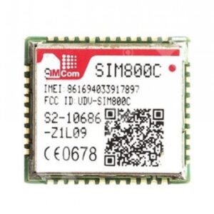
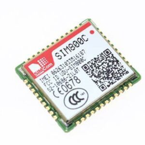
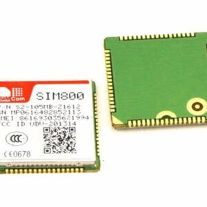
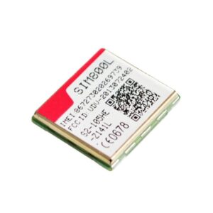
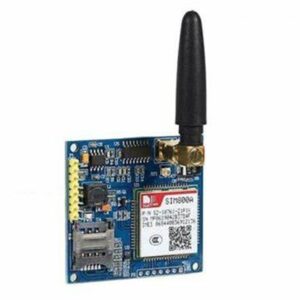
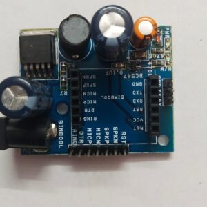
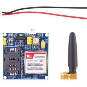
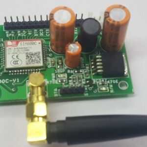
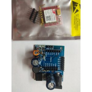
SIM800C Module with RS232 Interface
The SIM800C Module with RS232 Interface, operating within the 850 MHz, 900 MHz, 1800 MHz, and 1900 MHz frequencies. Its small size makes it convenient to use as a plug-in GSM modem. The baud rate can be adjusted using AT commands, with a default setting of 9600 baud. SIM800C Module with RS232 Interface only requires two wires (Tx, Rx) in addition to a power supply when interfacing with a microcontroller or host. Its compact design allows for easy integration into various customer designs.
Some notable characteristics of SIM800C Module with RS232 Interface
- The AT command interface is not
- The quad-band and dual-band versions are available.
- The voltage supplied ranges from 3.4 to 4.4V.
- GPRS multi-slot class 12/10 refers to a system that allows for efficient data transfer using multiple slots.
- Place and receive phone calls.
- Exchange text messages via SMS.
- Transfer GPRS data, such as TCP/IP and HTTP.
- Bluetooth utilizes firmware.
- The USB connector is used to update the firmware.
- The baud rate can be adjusted to any value between 9600 and 115200, with the default setting being 9600 upon factory reset. External speaker and mic connectors
- An interface can be selected between a hardware serial port and a software serial port.
- Features a robust TCP/IP protocol stack designed specifically for transferring Internet data over GPRS.
- The Power and connectivity are indicated by LEDs.
- There are two Reset switches available – one for the Arduino and one for the shield.
- Use the slide switch to alternate the shield’s connection between the Arduino and PC.
- The option to choose between hardware or software serial is available.
The steps to establish a connection are as follows:
- The GSM receives a -12v power supply.
- Place the SIM card inside.
- The power LED is illuminated.
- There are also two additional LEDs: the Status LED and the Network LED.
- For the readiness of the modem, the status LED will illuminate.
- After detecting a signal, the network LED blinks at a slightly slower rate than it did initially when searching for a connection.
- Connect to your computer using a USB to RS232 converter.
- Attach GSM transmitter to TTL receiver.
- Link GSM Rx to TTL Tx.
- Make sure to connect GND to your PC.
- To begin, launch Real term and adjust the port to 9600 baud rate. From there, transmit AT Commands to receive and send data seamlessly.
- The GSM commands are a set of instructions used in GSM networks. They allow users to perform various tasks such as sending messages, making calls, and accessing data services.
- Please provide a brief explanation for each command’s corresponding response.
- AT OK is the command used to initiate the command line.
- The module will be converted to text mode upon setting AT CMGF=1, confirmed with an OK response.
- Check the signal quality at CSQ CSQ:30,0.
- Using AT CMGS command, enter the desired mobile number and compose your message.
- Are you at CPIN? Is your SIM card activated and ready to use?
- The CNGS reading for Ctrl Z is currently at 0.
- It is permissible to deliver a message.
- CMGR=1 will display the initial message in the Inbox, which will then be accessed.
- Upon setting CMGD to 1, the initial message in the Inbox will be erased.
- Just remember to include the semicolon after the AT command. For instance, if you’re using the ATD command, your entry should look like this: “ATD1234567890;”.
- Respond to the incoming call with ATA OK.
- Please verify the firmware version at CGMR OK.
There are various uses for this technology.
- Fast deployment of mobility solutions
- High volumes of transactions
- Browse through the SIM’s phone book entries.
- Minimal downtime
- Convenient accessibility is readily attainable.
Instructions for linking SIM800C Module with RS232 Interface:
- Attach the 12v power supply to both the GSM and Arduino components.
- Link the GSM Rx to the Aurdino Tx.
- Attach the GSM transmitter to the Arduino receiver.
- Ground the GSM and Aurdino by connecting their respective GND pins.
- Simplify the following program.
There are no reviews yet.