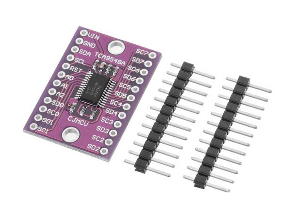
TCA9548A 8 Channel Extensions Development Board
Have you come across the ideal I2C sensor and want to connect multiple of them to your Arduino? However, you might have noticed that this chip has a fixed I2C address. As we know, having two devices with the same address on the SDA/SCL pins is not possible according to I2C protocol. Does this mean you’re out of options? Not if you have the amazing CJMCU TCA9548A 8 Channel extensions development board.
The CJMCU TCA9548A 8 Channel extensions development board offers an intriguing feature where it has a default I2C address of 0x70. Essentially, by sending a command, you can specify which I2C multiplexed output to communicate with and then easily access the desired board.
TCA9548A 8 Channel Extensions Development Board Uses a variety of breakout boards.
Specifications and Features of CA9548A 8 Channel extensions development board:
- These switches are capable of bidirectional translation from 1 to 8.
- Enables Hot Insertion.
- Reduced idle current.
- Introducing our 1-to-8 Bidirectional Translating Switches, the perfect solution for your translation needs. These switches provide seamless and efficient bi-directional translation capabilities between two languages. With their compact design and reliable performance, our 1-to-8 Bidirectional Translating Switches are a must-have for any language-translation situation.
- Boost Your Device Without Any Switch Channels Selected.
- The I2C Bus and the SMBus are both compatible.
- Inputs with a tolerance of 5 volts.
- Leveraging its robust design, this device boasts a latch-up performance that surpasses JESD 78, Class II standards with a current exceeding 100 mA.
Description of Pins:
Introducing our latest innovation, the Power Pins! These revolutionary pins are designed to provide a powerful grip on all types of fabric, making them ideal for your sewing and crafting needs. Say goodbye to flimsy pins that constantly slip and ruin your projects, and hello to strong and reliable Power Pins. Upgrade your sewing game with these game-changing pins today!
Vin is the designated power pin for the sensor chip, which requires a voltage range of 3-5 volts. The board can be powered by providing it with the same level of voltage as your microcontroller’s logic level. For instance, if you are using a 5V microcontroller such as Arduino, use 5V to power board.
- GND serves as a shared foundation for both power and logic components.
- These are the pins on the control side of I2C:
- This pin is known as SCL and it serves as the I2C clock for the chip. Connect it to your microcontroller’s I2C clock line.
- SDA is the chip’s I2C data pin, which should be connected to your microcontroller’s I2C data line.
- The reset pin, known as RST, is used to reset the multiplexer chip. By default, it is pulled high, but can be connected to ground in order to reset the chip.
- The address selection pins for the multiplexer are A0, A1, and A2. When left untouched, the default address for the multiplexer is 0x70 with all three pins pulled low. However, if you connect them to Vin, you can set the address to any value between 0x71 and 0x77.
- If A0 is set to a high value, the address will increment by 1 as it represents the least significant bit.
- The 2nd-lowest-significant bit of A1, when set high, will result in a 2-unit increase in the address.
- The significance of A2 is the 3rd-lowest; if it is pulled high, a corresponding increase by 4 will be seen in the address.
- SDx and SCx refer to two different terms used in this context.
- Included in the pins are 8 sets of SDx and SCx, ranging from SD0/SC0 to SD7/SC7. These particular pins are known as the multiplexed ones and each functions as its own individual I2C bus. This means that you can have up to 8 I2C devices with matching addresses, as long as they are connected to their own designated bus.
- Ensure that pullup resistors are added when using a chip or breakout without built-in I2C pull-ups. Fortunately, Vin can be set at 3.3V while still having these pins pulled up to 5V, as they are compliant with 5V operation.
- The desired program is to be implemented as planned.
- Utilize this small tool to assist in choosing the port.
- TCAADDR, also known as the TCA address, is a hexadecimal value of 0x70.
- Selects a case based on the input value given.
- If the number is greater than 7, it will be returned.
- The transmission will start at TCAADDR, as per usual.
- Instead of repeating the same code, use tcaselect(0) through tcaselect(7) to designate which multiplexer to set up. Keep in mind that if any of your I2C devices have an address of 0x70, you’ll need to connect one of the Add pins on the TCA9548A 8 Channel extensions development board. to Vin to prevent conflicts. Simply choose any address between 0x70 and 0x77 that is not already in use and you’ll be all set.


There are no reviews yet.