Wireless Four Button RF Remote Control Module
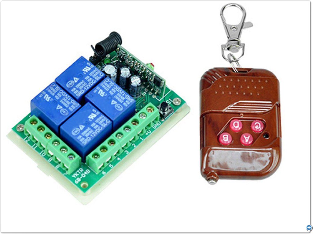
The Wireless Four Button RF Remote Control Module, equipped with a Non-Locking mode, includes four fixed code radio receiver circuits. These circuits generate a four-bit data output code that corresponds to the remote control module, allowing for the effortless assembly of a wireless receiver circuit.
Wireless Four Button RF Remote Control Module are commonly used by many home electronics enthusiasts and in the development of various industrial remote control electronic products. They serve as effective single-chip signal input sources, making them particularly useful for students and colleges in electronic circuit design, including graduate level projects involving the remote control circuit component.
The remote control has four buttons, each corresponding to a data bit on the receiving board’s output pins: D0, D1, D2, and D3.
By pressing the buttons, the corresponding data bit will be transmitted as a high output.
Please exercise caution when handling the receiver module. Avoid touching the onboard copper coil (inductor), as even slight physical movement can alter its inductance value and potentially affect the circuit’s performance.
The process of Wireless Four Button RF Remote Control Module:
When a key is pressed, the IC connects to the power supply battery and begins transmitting packets at a frequency of 315 Mhz. These packets contain both its ID and Data byte, identifying which key was pressed. This data is commonly utilized in remote control applications.
The pre-programmed unique ID of each transmitter is set during manufacturing and cannot be altered. For secure purposes, the receiver board typically stores this ID in its memory, allowing it to only respond to known transmitter IDs.
The remote’s RF component is a SAW-based 315 Mhz transmitter that can be picked up by any ASK RF Receiver and decoded by its corresponding chip.
Kindly take note of the following information included in this message.
The Wireless Four Button RF Remote Control Module is initially set to Non-Locking mode.
The remote control is available in various operating modes, including Non-locking, Self-Locking, and Interlocking. Wireless Four Button RF Remote Control Module included specifically comes in Non-Locking Mode.
The door does not have a lock.
Jog output data pin level can be used to control remote signals, similarly to jogging. When the remote data foot is high, the signal disappears and is immediately restored to a low level. This is useful for applications like electric doors, door locks, and SCM docking, which only require a high-level circuit instead of other circuits.
The self-locking mechanism allows for secure and reliable closure without the need for external locks or additional tools.
The Data output pin triggers the operating logic to flip, allowing data to be held until the next remote data changes. This enables self-locking for up to four simultaneous remote controls, such as lighting control.
The pieces of this puzzle fit together perfectly, creating a solid and secure structure that cannot be easily taken apart.
In terms of practical applications, the Output results in the road being able to receive the signal and maintaining a high state, corresponding to the received data. The only way to return to the initial state is by activating all four interlockings, as seen in circuits like position switches for electric fans.
The specifications of the Wireless Four Button RF Remote Control Module, along with its distinct features, have been listed below.
- This Wireless Four Button RF Remote Control Module is a handy and convenient device that allows you to remotely operate your electronic devices.
- The modulation mode being used is ASK, which stands for Amplitude Modulation.
- Types of encoders include fixed code.
- The decoding receiver board receives the encoded signals from the remote control and decodes them to determine the intended action.
- Operating voltage for the receiver: 5V DC.
- The receiver sensitivity is measured at -98dB.
- The seventh leg includes VT, D3, D2, D1, D0, 5V and GND.
- Upon receiving a valid signal, VT will output high and activate the relay.
- The dimensions are 7 x 22 x 41 mm.
- The pin connection and functions refer to the various pins and their respective roles in a device.
- Indication of the VT output status.
- The output of the data from D3.
- The output of the D2 data.
- The data output for D1.
- Output data.
- Positive 5-volt power supply.
- The negative power supply for GND.
- The antenna terminal is connected by ANT.
- There are a total of eight external receiver module interfaces. “5V” denotes a positive power supply, while “D0, D1, D2, D3” indicate the output. “GND” refers to the negative power supply, and “ANT” indicates the antenna terminal connection.
- Regarding the distance requirements, for optimal use of a quarter-wavelength antenna, a 50-ohm single wire with a length of approximately 17cm is typically recommended.


There are no reviews yet.