X9C104 Digital Potentiometer Module
The X9C104 digital potentiometer module allows for the simulation of mechanical potentiometer control. Equipped with 99 series-connected resistors, the integrated circuit functions with a microcontroller to determine the placement of the center pin of the “potentiometer” among the 100 available points (at either end or between resistors).
The X9C104 digital potentiometer module includes 100 resistors, each with a 1K ohm value. Using the pins, we can choose the desired number of resistors and digitally adjust the overall resistance of the potentiometer. It has a power dissipation of 10 mW and can handle resistors with a maximum current of 4.4 mA.
X9C104 digital potentiometer module boasts numerous applications, serving as both a resistive divider and variable resistance. It is utilized in various setups alongside operational amplifiers or other analog circuits.
Could you please provide a different way of expressing the following paragraph while maintaining the same tone?
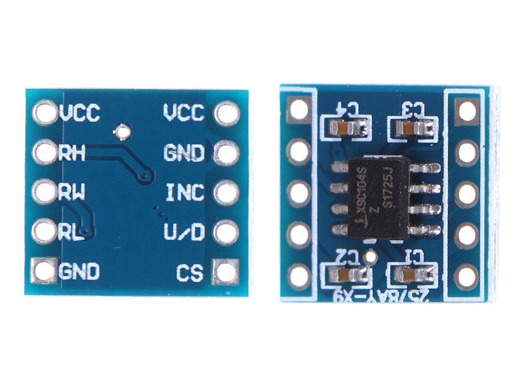
The VCC supplies a constant 5V.
INC adjusts the number of resistors in series, which is linked to the mechanical potentiometer at the variable terminal. The negative terminal of INC scans for incoming signals. In order to increase or decrease, one must switch the INC (toggle) in the direction of the variable terminal, as denoted by U / D.
You can use the U/D control to determine the direction in which the terminal variable moves (Up / Down).
Equivalent terminals on a mechanical potentiometer, such as the RH and RL terminals, have a fixed resistance value. For example, potentiometer X9C104 always has a resistance of 100 ohms. However, if a different resistance level is required, other members of the X9C family, such as 102, 103 or 503, can be used instead.
The RW and terminal are both equivalent to the mechanical potentiometer.
CS, short for chip select, is used to enable or disable the module.



There are no reviews yet.